Truma Combi 4E/6E:
Installation & Wiring
A step-by-step technical guide to installing the Combi system to UK Gas Safe and electrical standards.
Professional Installation Overview
Installing a Truma Combi is a significant undertaking that involves gas, 12V DC, 230V AC, and plumbing systems. While a competent DIY builder can handle the physical mounting and ducting, the final gas and 230V connections should always be verified by a qualified professional in the UK.
UK Compliance Alert
In the UK, any gas installation in a vehicle used for hire or reward (and increasingly for private insurance purposes) must be signed off by a Gas Safe registered engineer with the LPG/Motorcaravan qualification.
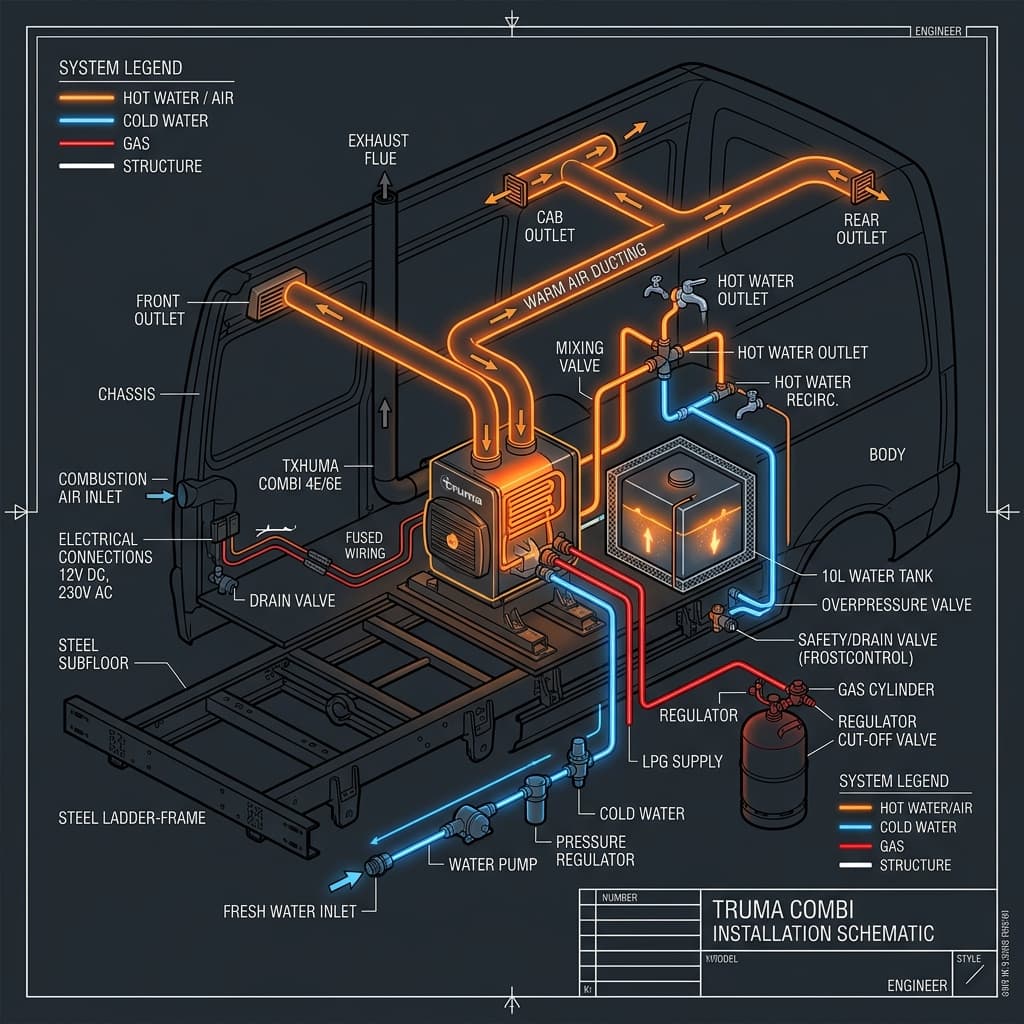
Official Installation Schematic
Download the high-resolution A3 PDF containing all official Truma installation callouts, cable sizing, and UK-specific safety notes.
LPG Gas Safety
The Truma Combi requires a 30mbar gas supply. The connection on the unit is an 8mm olive compression fitting. It is vital that the gas pipework is properly secured and that a gas isolation valve is fitted in an accessible location dedicated to the heater.
- Use 8mm copper pipe (plastic is not permitted for gas in UK vans).
- Ensure the gas locker is sealed and vented through the floor.
- Perform a leak-down test after installation.
230V AC Wiring
For the "E" variants, the 230V connection powers the internal 900W/1800W heating elements. This should be wired via a 13A fused spur from your RCD-protected consumer unit.
Cable Specification
Use 1.5mm² or 2.5mm² 3-core flexible cable (Arctic Blue or similar). Avoid using solid-core domestic twin and earth, as it can fracture due to vehicle vibration.
Flue & Cowl Positioning
The balanced flue cowl must be mounted on a flat vertical surface on the side of the van. Crucially, it must not be placed directly under an opening window, as exhaust gases could enter the vehicle. If a window is nearby, a window switch must be fitted to the Truma to disable the heater when the window is open.
Plumbing & FrostControl
The hot and cold water connections use 10mm or 12mm semi-rigid pipe (e.g., John Guest Speedfit). The **FrostControl valve** must be installed in the cold water feed before it enters the heater. Ensure the discharge pipe from the FrostControl valve goes through a hole in the van floor to allow for safe drainage.